About Hampi and the project
Hampi, celebrated as one of the richest and largest cities in the world during its prime, was the capital city of the famous Vijayanagara Empire. Today, this great city is in complete ruins.
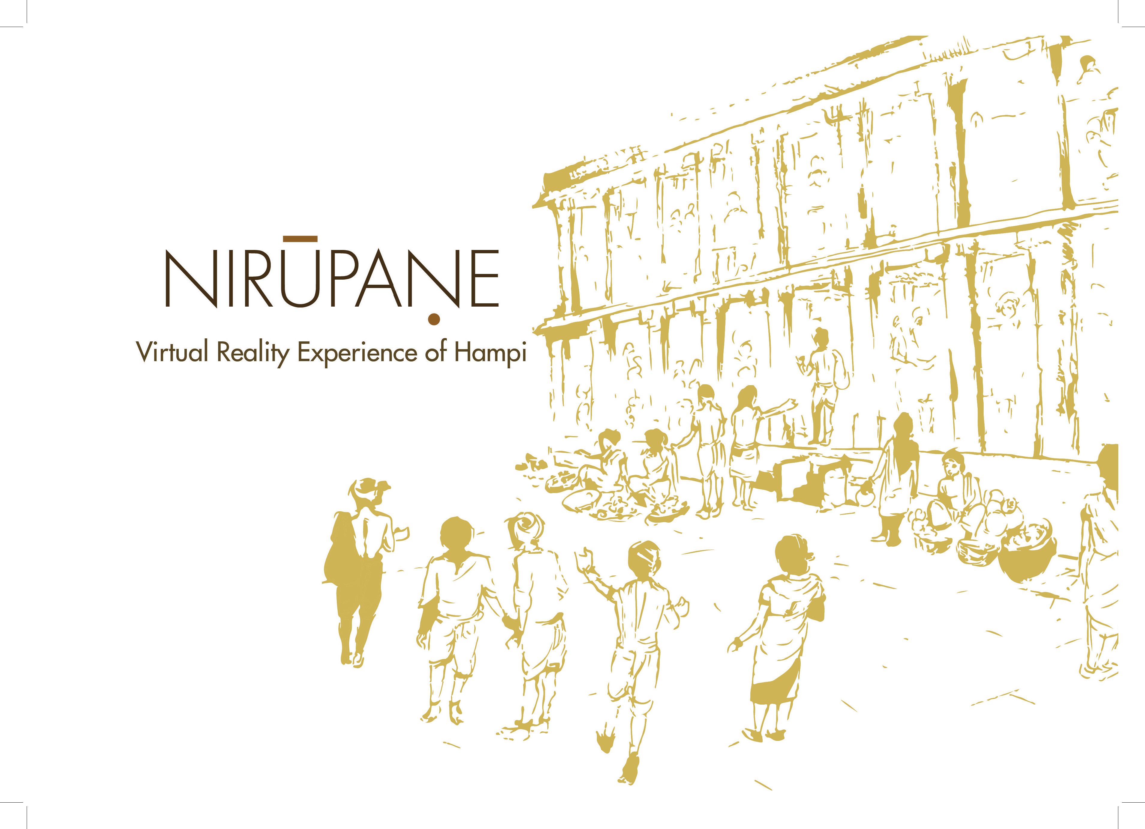
For conserving our heritage for posterity, efforts are being made to understand and recreate the architecture, arts and artifacts in the context of the Hampi Bazaars. This project is part of Indian Digital Heritage Project, Department of Science & Technology (DST), Government of India.
Using the present technology of Virtual Reality (VR), NIRUPANE, is an endeavor to recreate the glorious and exhilarating experience of the Hampi Bazaars amid narratives and stories, eventually appreciating the caliber Vijayanagara Empire.
Hampi
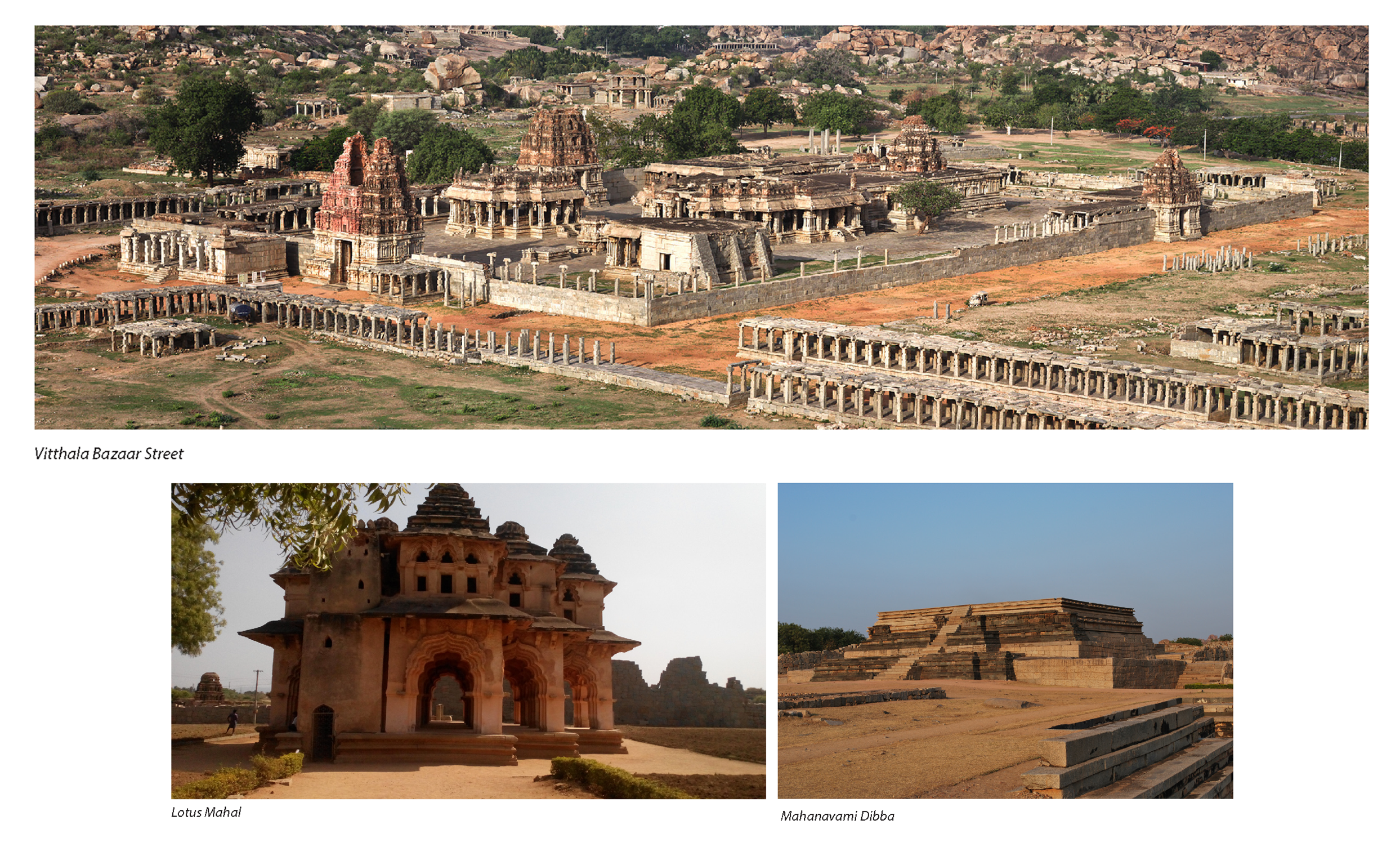
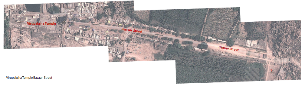
Virupksha Bazaar Street
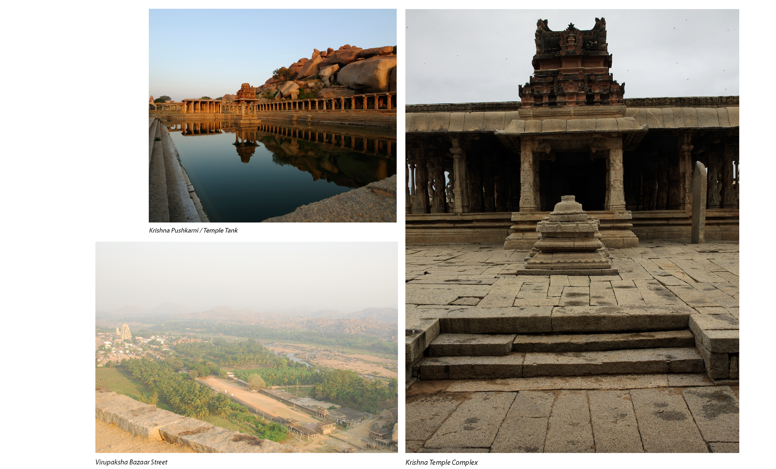
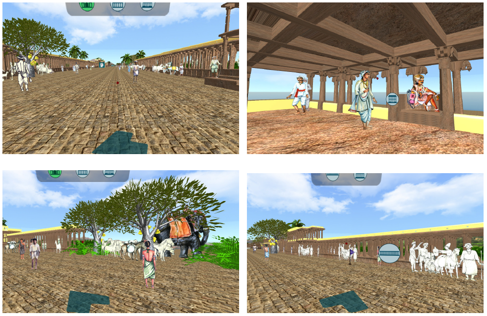
The street in front of the Virupaksha Temple complex is 800m long and over 13m wide with the Virupaksha Temple on one end and the Nandi Mantapa on the other. The street has more than 50 structures. The temple street was also called the Rathavidhi as the temple car or Ratha was pulled during the annual festival here. This chariot festival can be seen even today. One of the salient features of the Virupakshapura was that a weekly market was held regularly. The farmers of surrounding areas brought their goods and services to exchange or to purchase items like precious ornaments, cloths etc. that were sold here. As the commercial activities grew, the merchant’s set up their permanent shops around the temple. In these Bazaars each class of men belonging to each profession were said to have shops adjacent to one another.
The temple was the center of all activates of the kingdom. The temple denoted the inner space or the ritualistic space and the bazaar street denoted the civic space. In the beginning the Virupaksha market might have had goods in view of the needs of the temple. Later as more people started living around the bazaar, food and other consumer materials for the people were sold.
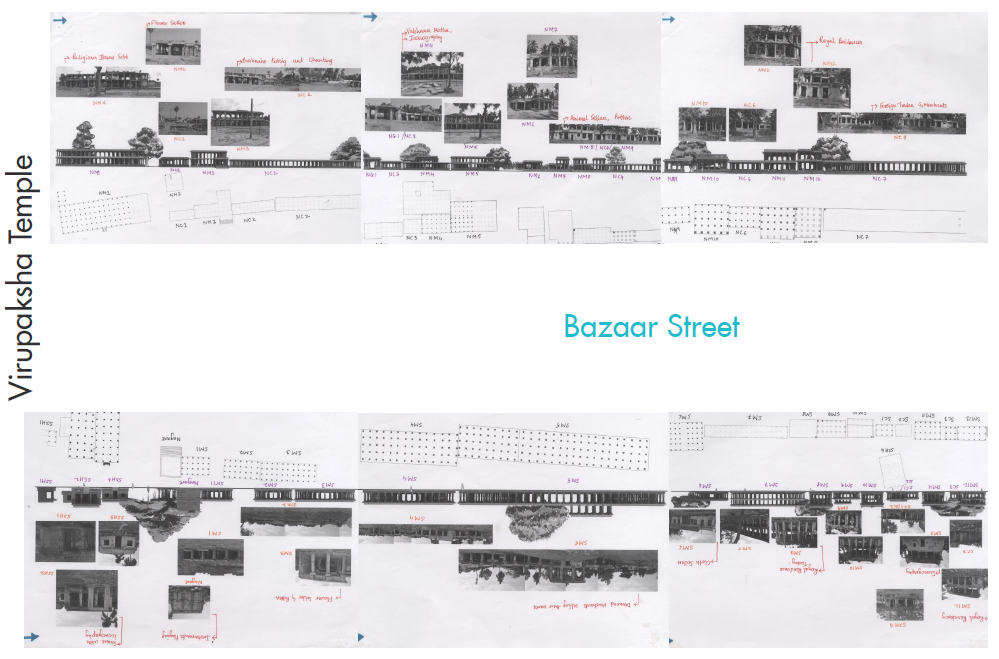
Street Plan
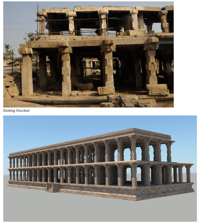
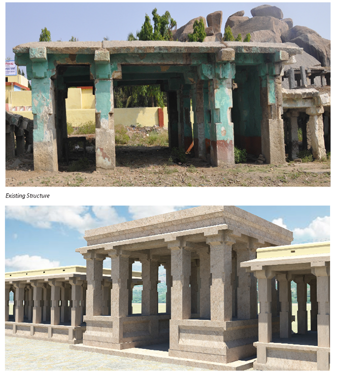
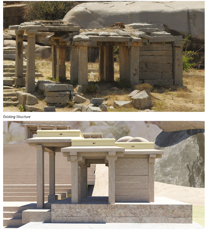
A plan of the street was laid out based on the street map. The present structures and the reconstructed structures were laid side by side to get a better view of the whole street. From this plan, those structures which could be shown in detail was decided upon.
Prototyping
Recreation of structures digitally
Attempt 1: Using images to make the 3D structure
In this first attempt, it was understood that each structure on the street was ultimately a cube with six faces. Images of these six face could be used to create an illusion of the structure. Good quality images were taken and placed in Unity 3D. Now Unity 3D has a feature where a two dimensional image can be made to feel three dimensional. But the problem here was, these structures are pillared and the user could see through the pillars. Here, the illusion of the 3D structure was revealed. This attempt failed completely.
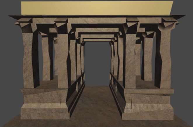
Attempt 2: Reducing the poly count
These 3D models were made using Autodesk Maya software. The details in them increased the polygon count in each model thereby increasing the number of triangles, vertices and surfaces. So with the idea that by reducing the polygons, the model would become simpler and the size would be reduced; each model was reworked on. But this again had an issue. These models were made in a way to accommodate maximum detail in them. Any change in the polygons, made the model deform in shape. The shape was lost as the detailing was lost. Had the models been made using lesser details, reducing the polygon count would have helped. This attempt did not work as well.
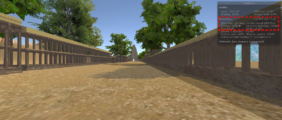
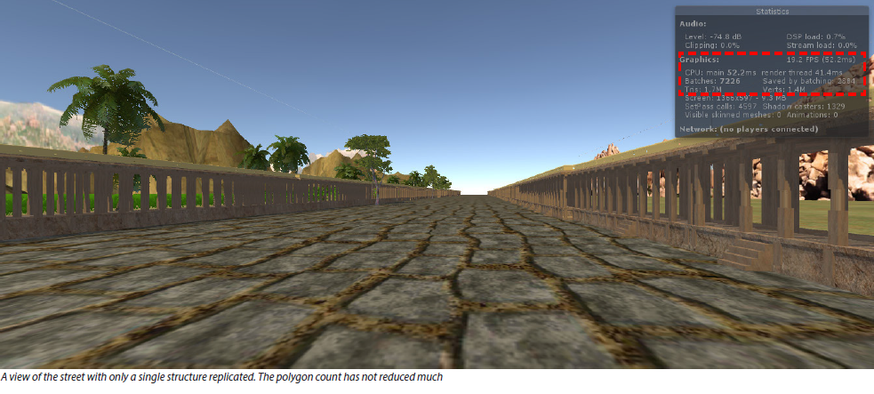
Attempt 3: A single model to build the whole street
In this attempt, the whole street was created using only a single model. For this, the less detailed and the simplest model with the lowest polygon counts was decided upon. This model was then replicated through the whole stretch of the street. At first it felt that this might work but there were 2 issues here. The first being that the whole street would look the same and the second that as the number of structures increased, the polygon count also kept on increasing, making the file heavy. This attempt also did not work.
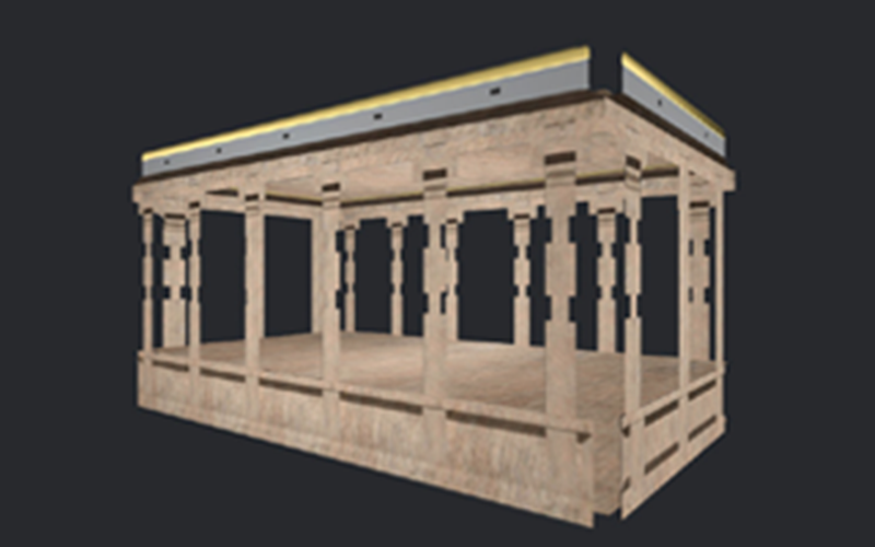
Attempt 4: Using Level of Detail (LOD) in Unity
Unity 3D has a plug-in called Simplygon. This plug-in basically simplifies the 3D models to suit game play and mobile VR. This plug-in uses the idea of Depth of Field. Basically, the structures closest to the user would be viewed in great detail and the structure farthest would have least detail. Three different versions of the same model was created and used based of the users distance and the field of view. This seemed to be a good option to optimize the models of the structure. But there was an issue here as well. The 3 versions of a single model were present all the time in the environment denoting that all the 50 models of the structures of the street had 3 versions each at the same time placed on the street. The file size shot up tremendously.
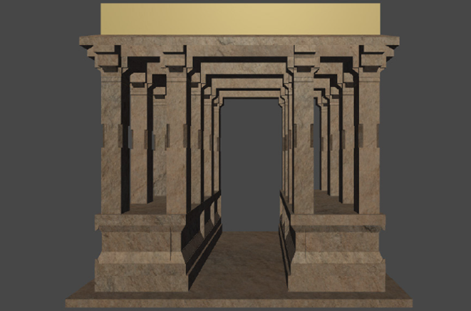
LOD 0
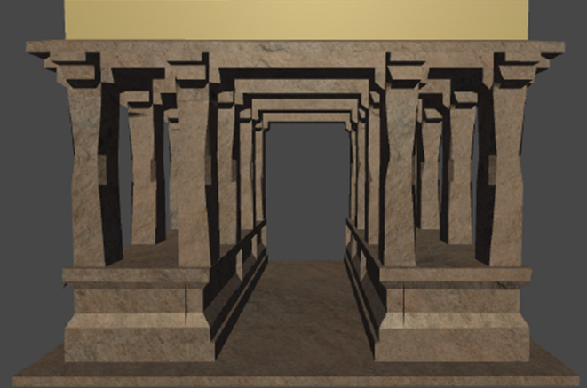
LOD 1
LOD 2
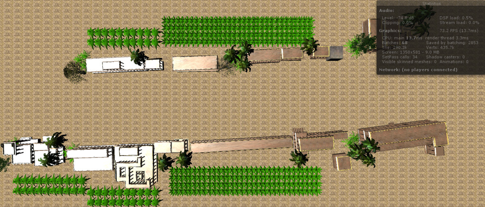
Attempt 5: Breaking the street into smaller parts
The next best option left was to break the whole street into parts. The Level of Detail experiment would work if the file size could be controlled. This could be done in the best way by dividing the street into parts. The street was divided in such a way that each part had 20 structures and all these structures had their 3 versions based on their LOD’s. This group of the 20 structures were divided into scenes in Unity 3D. Three different scenes were created. In this way the detailing of the street was not lost and all the structures were also visible to the viewer completely. This division would help as the other details on the street like the characters could now be added. The file size reduced considerably in the parts but as a whole it was quite huge, but there way no getting away with that. This was going to work and it did.
This attempt and re-attempt took a lot of time to figure out. More than a month was spent in deducing the right way to create the virtual environment. But it a good learning to understand the nuances involved in making a virtual experience.
Interactions & Further Development
The major interactions can be categorized as
> Movement:
Since it was either the Google Cardboard or the HMD connected wth a Bluetooth controller that was going to be used to control the user’s actions in the virtual world, the trigger on them could be used for starting and stopping any
movement. On the Cardboard, the magnet acted as a trigger and on the Bluetooth controller, the joystick was mapped to forward and backward movement.
The position of the head would determine the direction in which the user would move and clicking of the trigger button would enable the user to start and stop moving.
> Interactive Audio Spots:
There are two kind of interactive audio spots on the street namely:
- Interactive spot with only audio describing the relevance of the structure
- Interactive spot in the middle of the street with only audio describing the relevance of the street
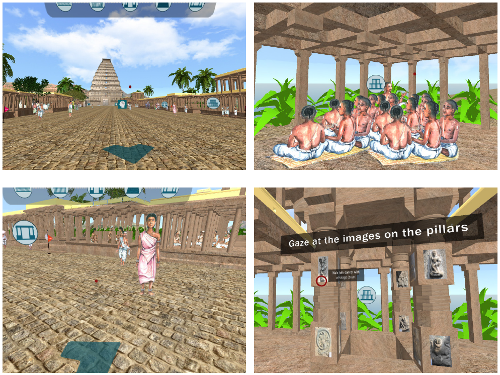
> Immersive Spots:
Apart from the audio interactive spots on the bazaar street an attempt was made to give the viewer an inside look onto the structures. If one goes to Hampi today, one can only walk around freely on the street and cannot enter any of the structures as they are cordoned off from public.
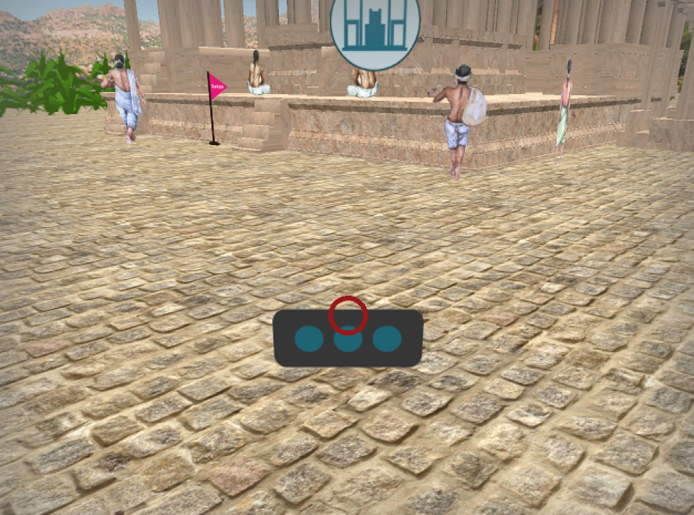
> Menu Button:
This button is placed near the feet of the user and would come into view if the user looks down near the feet in the virtual world. When clicked, four actions are visible.
Different scenes- There are two scene icons apart from the active scene visible. One can click on these icons and directly jump to a different scene.
Map: On clicking the map the user will be able to view the map of only that part of the street that is visible in the current scene. The user’s current location and the interactive spots in the scene is also visible. The spots that have already been visited by the viewer is colored in green.
Quit Application: One can quit the whole application from here.
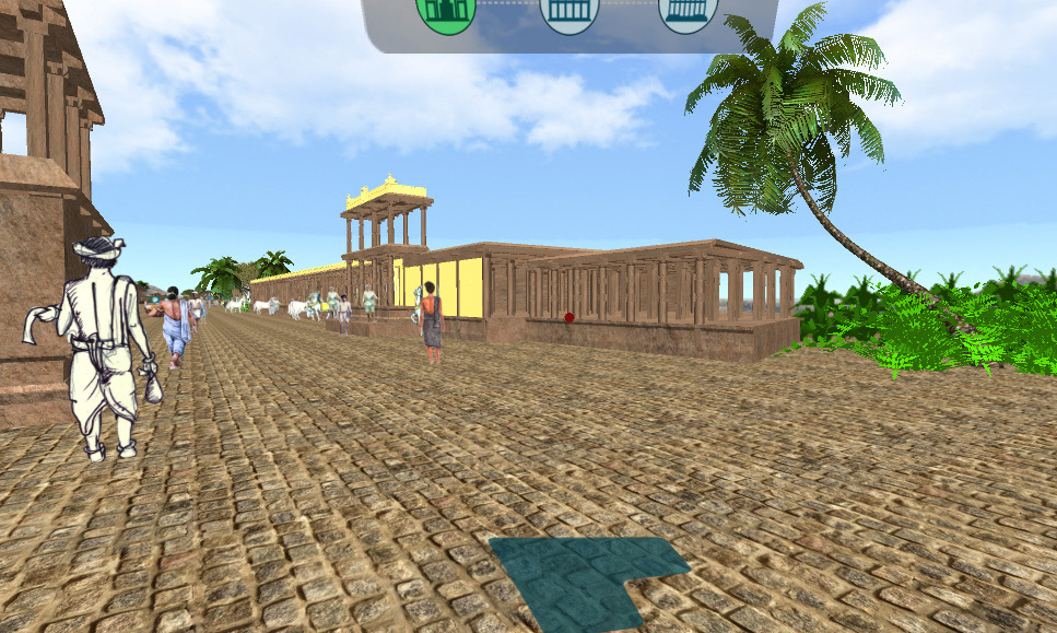
> Dashboard:
The dashboard is visible to the viewer at all times placed a little above the eye level. This dashboard highlights all the interactive spots visited by the user.
Final Output
Featured in ALPAVIRAMA
When the prototype was almost ready, there was a unique opportunity to showcase the project at an exhibit, “Videos on the Edge” at National Institute of Design, Ahmedabad. This was part of the Alpavirama, an Asian Short and Documentary Film Festival. This exhibit spoke about Space-Time Experiments with the Moving Images.